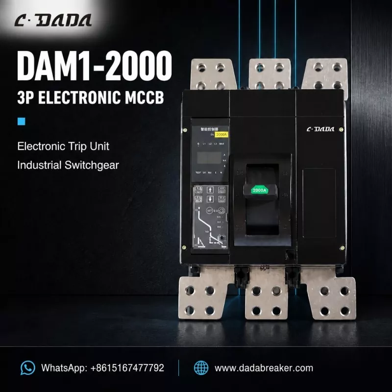
Durable Moulded Case Circuit Breaker Factory
CDADA is a professional manufacturer and supplier of Moulded Case Circuit Breakers. This product series constitutes one of our core offerings, backed by 40 years of experience dating back to our inception. With a comprehensive range of models that comply with numerous standards, global buyers can select our products with complete confidence.
What Is a Moulded Case Circuit Breaker?
A Moulded Case Circuit Breaker (MCCB) is a compact, enclosed low-voltage protection device designed to safeguard electrical distribution systems against overloads, short circuits, and ground faults. Encapsulated within a thermosetting plastic housing, MCCBs operate at rated voltages up to 690V AC (50/60Hz) with current ratings ranging from 10A to 2000A, serving as the workhorse protection device across industrial, commercial, and infrastructure applications.
The defining characteristic of MCCBs lies in their moulded case construction—a high-strength thermosetting plastic enclosure that provides Class II insulation (double insulation) between live internal components and the external operating interface. This design ensures operator safety while maintaining compact dimensions and high breaking capacities up to 100kA at 380/415V.
Unlike Air Circuit Breakers (ACBs), MCCBs feature fixed, non-maintainable designs (in most cases) with sealed internal mechanisms, offering cost-effective protection for secondary distribution circuits where regular maintenance access is not required.
MCCB Product Categories & Configurations
| Classification | Type | Current Range | Key Characteristics |
| Trip Unit Technology | Thermal-Magnetic | 10A – 800A | Bimetallic overload + magnetic short-circuit, fixed/adjustable settings, economical |
| Electronic LSIG | 100A – 2000A | Microprocessor-based, adjustable curves, communication-capable, precise protection | |
| Installation Method | Fixed | 10A – 2000A | Direct busbar connection, permanent installation, lowest cost |
| Plug-in | 100A – 1600A | Base-mounted body, withdrawable for maintenance, reduced downtime | |
| Withdrawable | 250A – 2000A | Draw-out mechanism, full isolation capability, safety shutters | |
| Pole Configuration | 2-Pole | 10A – 800A | Single-phase systems, DC applications |
| 3-Pole | 10A – 2000A | Standard three-phase industrial applications | |
| 4-Pole | 16A – 2000A | Three-phase with neutral protection, adjustable neutral settings (50-100%) | |
| Breaking Capacity | Standard (S1) | 16kA – 50kA | General distribution, low fault level networks |
| High (H1) | 65kA – 85kA | Industrial mains, motor control centers | |
| Ultra-High (H2/H3) | 100kA – 200kA | Power generation, heavy industry, infrastructure | |
| Selectivity Category | Category A | ≤400A | No intentional short-time delay, instantaneous trip |
| Category B | ≥400A | Short-time withstand (Icw), selective coordination with delay |
Frame Size Architecture:
Compact Frame: 10A – 160A (Panelboard mounting, DIN rail compatible)
Medium Frame: 160A – 630A (Motor protection, distribution boards)
Large Frame: 630A – 1600A (Main distribution, busbar systems)
Maxi Frame: 1600A – 2000A (Infrastructure, power generation)
Core Functions & Protection Capabilities
Fundamental Protection Functions
| Function | Mechanism | Technical Parameters |
| Overload Protection (L) | Bimetallic strip thermal expansion | 0.7 – 1.0 × In setting, inverse time curve, 40°C reference ambient |
| Short-Circuit Instantaneous (I) | Electromagnetic solenoid plunger | Fixed: 5-10 × In, Adjustable: 2-15 × In, <20ms operation |
| Short-Circuit Delay (S) | Electronic timing circuit | 0.1s – 0.5s delay, 2-10 × In setting, selective coordination |
| Ground Fault (G) | Vector sum current sensing | 20-100% of In, 0.1s-1.0s delay, core-balance or residual method |
| Current Limiting | High-speed repulsion contact system | <10ms opening time (≤630A), <15ms (≤1600A), let-through energy reduction |
| Undervoltage Release | Voltage sensing coil | 35-70% Un tripping, 0.1s-3s adjustable delay |
Advanced Electronic Trip Unit Features
Modern microprocessor-based releases provide:
True RMS sensing: Accurate measurement of distorted waveforms
Zone Selective Interlocking (ZSI): Bus-tie and incoming device coordination
Communication protocols: Modbus, Profibus, Ethernet/IP, BACnet integration
Power quality monitoring: Voltage, current, power factor, harmonics, energy metering
Predictive maintenance: Contact wear indication, operation counter, temperature monitoring
Application Environments & Use Cases
| Industry Sector | Specific Application | Typical Specifications |
| Commercial Buildings | Main distribution boards, panelboards, tenant metering | 125A-800A, thermal-magnetic, plug-in, 25-65kA Icu |
| Data Centers | UPS distribution, PDU protection, busbar tap-offs | 250A-1600A, electronic LSIG, 100kA+ Icu, communication-enabled |
| Manufacturing Plants | Motor control centers, machine tools, welding equipment | 63A-630A, motor protection curves, current limiting, 65kA Icu |
| Oil & Gas | Drilling rigs, refineries, offshore platforms | 400A-1600A, tropicalized (T2), corrosion-resistant, 85kA Icu |
| Renewable Energy | Solar combiner boxes, wind turbine switchgear, battery storage | 250A-1250A, 1000V DC capable, extended temperature range (-25°C to +70°C) |
| Infrastructure | Metro traction power, airport baggage systems, water treatment | 800A-2000A, withdrawable, high mechanical endurance (10,000+ cycles) |
| Healthcare | Hospital main distribution, medical imaging equipment, emergency power | 400A-1600A, 4-pole with neutral protection, dual-source transfer compatibility |
Manufacturing Process & Production Workflow
Precision Manufacturing Sequence
Raw Material IQC → Thermosetting Plastic Molding → Contact System Fabrication → Arc Chute Assembly → Mechanism Integration → Trip Unit Installation → Primary Assembly → Calibration & Testing → Final QC → Packaging
Critical Manufacturing Stages
| Stage | Process Details | Quality Control Points |
| Thermosetting Plastic Molding | BMC (Bulk Molding Compound) injection molding at 150-180°C, 1500-3000 bar pressure, 60-120s cure time | Dimensional tolerance ±0.1mm, surface finish Ra 1.6, tracking index >600V, UL 94 V-0 flammability |
| Contact System Fabrication | Silver-plated copper contacts (AgNi 90/10 or AgCdO), CNC-machined contact arms, brazing in nitrogen atmosphere | Silver thickness 8-12μm (XRF verified), contact resistance <100μΩ, hardness HV 100-150 |
| Arc Chute Construction | Steel splitter plates (ferromagnetic), ceramic arc grids, deionizing chambers, optimized arc runner geometry | Magnetic flux density verification, dielectric strength 2.5kV, dimensional consistency ±0.05mm |
| Operating Mechanism Assembly | Spring steel charging systems, quick-make/quick-break mechanisms, trip-free override, energy storage springs | Torque consistency ±5%, mechanical endurance 10,000 cycles, trip force 5-15N |
| Trip Unit Integration | Thermal bimetal calibration (Inconel/copper), magnetic coil winding, electronic PCB assembly, firmware programming | Time-current curve verification, ±10% current accuracy, ±20% time accuracy at 2×In |
| Final Assembly | Modular construction, terminal torque marking, sealing of adjustment covers, handle mechanism integration | Dielectric withstand 3kV/1min, insulation resistance >100MΩ, contact alignment verification |
Primary Raw Materials & Component Specifications
| Component | Material Specification | Supplier Standards | Key Properties |
| Moulded Case Housing | BMC (Bulk Molding Compound) DMC-2 or SMC fiberglass-reinforced polyester | IEC 60664-1, UL 94 V-0 | Tracking index >600V, heat resistance 180°C, dielectric strength >15kV/mm |
| Main Contacts | Electrolytic copper (Cu-ETP) C11000 + Silver-nickel plating (AgNi 90/10) | ASTM B152, IEC 60368 | Conductivity ≥100% IACS, arc erosion resistance, oxidation stability |
| Arcing Contacts | Silver-tungsten carbide (AgWC 70/30) or Copper-tungsten (CuW 80/20) | ASTM B702 | High arc erosion resistance, low welding tendency, contact resistance <200μΩ |
| Contact Springs | Beryllium copper (CuBe2 C17200) or Stainless steel 301 | ASTM B196, ASTM A240 | Fatigue life >20,000 cycles, consistent contact pressure 8-12N/mm² |
| Arc Splitter Plates | Cold-rolled steel SPCC-SD with ceramic coating | JIS G 3141 | Magnetic permeability >2000, heat resistance >1000°C, arc quenching efficiency |
| Operating Springs | Oil-tempered carbon steel SWOSC-V or 17-7PH stainless steel | JIS G 3560 | Tensile strength 1800-2000MPa, relaxation resistance <5% at 20 years |
| Bimetallic Elements | Inconel/copper composite (ASTM TM2) or Passivated steel/brass | ASTM B388 | Deflection rate 0.15-0.25mm/°C, stability ±3% over 20 years |
| Electronic Components | Industrial-grade PCBs, Hall-effect sensors, ARM Cortex processors | IEC 60721-3-3, IEC 61000 | Operating temperature -25°C to +70°C, EMC immunity Level 3 |
| Terminals | T2 copper (C11000) with tin or nickel plating | ASTM B187 | Current density 1.2-1.5 A/mm², torque withstand 15-50Nm |
Standards Compliance & Testing Protocols
International Standards Framework
| Standard | Scope | Applicable Ratings |
| IEC 60947-2 | Low-voltage switchgear - Circuit-breakers | Global baseline for MCCB design, performance, testing |
| EN 60947-2 | European harmonized version | CE marking, EU market compliance |
| GB/T 14048.2 | Chinese national standard equivalent | CCC certification, China market |
Mandatory Type Tests (IEC 60947-2)
| Test Category | Specific Test | Acceptance Criteria |
| Dielectric Performance | Power-frequency withstand (2kV-3kV/1min) | No breakdown, no flashover, leakage current <2mA |
| Impulse withstand voltage (8kV 1.2/50μs) | No disruptive discharge | |
| Temperature Rise | Continuous current at rated In | Terminals ≤80K (silver-plated), ≤65K (bare copper), case ≤40K |
| Short-Circuit Breaking | Ultimate breaking capacity (Icu) - 3 operations | Successful interruption, no permanent damage, dielectric recovery |
| Service breaking capacity (Ics = 50-100% Icu) | 3 operations, continued serviceability, contact wear <50% | |
| Short-Time Withstand | Icw for 0.5s or 1s (Category B only) | No deformation, contact welding, or insulation damage |
| Mechanical Endurance | No-load operations (typically 8,000-20,000 cycles) | <5% parameter drift, no mechanical failure, torque consistency |
| Electrical Endurance | Load operations at rated current (typically 1,000-6,000 cycles) | Contact wear <50%, trip characteristics maintained |
| Trip Unit Verification | Overload release at 1.05×In (no trip), 1.3×In (trip <2h) | Conventional tripping time compliance |
| Short-circuit release at 5×In, 10×In | Instantaneous operation <0.1s | |
| Current Limiting | Let-through energy (I²t) verification | Peak current limitation, energy reduction vs. prospective |
Factory Quality Control & Inspection Standards
Incoming Material QC (IQC)
| Material | Inspection Items | Sampling Plan | Equipment |
| BMC plastic compound | Glass fiber content, viscosity, cure characteristics | Per batch, COA verification | Rheometer, DSC analyzer |
| Copper contacts | Chemical purity (≥99.9%), conductivity, hardness | AQL 0.65, ISO 2859 | Spectrometer, conductivity meter |
| Silver plating | Thickness 8-12μm (XRF), adhesion (tape test), porosity | 100% visual, 5% XRF check | X-ray fluorescence, metallurgical microscope |
| Bimetallic strips | Deflection rate, stability, resistance | Per batch, sample testing | Thermal oven, resistance bridge |
| Steel components | Hardness HRC 38-45, dimensional tolerance | AQL 1.0 | Rockwell hardness tester, CMM |
| Electronic components | Function test, parameter verification, solderability | 100% AOI, 5% functional | LCR meter, oscilloscope, X-ray inspection |
In-Process Quality Control (IPQC)
| Station | Control Parameters | Frequency | Method |
| Injection molding | Temperature 150-180°C, pressure 1500-3000 bar, cure time | Every cycle | SCADA monitoring, SPC charts |
| Contact assembly | Contact gap, pressure, alignment, silver thickness | Every 100 units | Force gauge, optical comparator, XRF |
| Arc chute assembly | Splitter plate spacing, magnetic circuit integrity | Every 50 units | Go/no-go gauges, flux density meter |
| Mechanism calibration | Spring charge force, trip-free function, toggle operation | Every unit | Automated test bench, force-displacement curves |
| Trip unit testing | Time-current curve verification, ambient compensation | 100% | Primary injection test set (500A-10,000A), data logging |
In-Process Quality Control (IPQC)
| Test Item | Standard | Sample Size |
| Dielectric withstand voltage | 2.5kV AC/1min (≤690V rated) | 100% |
| Insulation resistance | >100MΩ @ 500V DC | 100% |
| Contact resistance | <100μΩ per pole at rated In | 100% |
| Timing characteristics | Close/trip time, mechanical endurance 5 cycles | 100% |
| Trip curve verification | 1.05×In (no trip), 1.3×In or 2.5×In (trip) | 100% |
| Visual & dimensional inspection | Zero defects on critical dimensions (IP rating, marking) | 100% |
Production Infrastructure & Manufacturing Capability
Advanced Production Equipment
| Equipment Category | Machine Specification | Function | Capacity |
| Thermosetting Injection Molding | 300-ton BMC injection press (Buhler/Engel) | MCCB case, cover, arc chute housing production | 2,000 cases/day |
| CNC Machining Center | 5-axis vertical machining center (Mazak/DMG Mori) | Precision contact machining, complex geometries | 8,000 contact sets/month |
| Stamping & Forming | 100-ton progressive die press | Copper busbar forming, contact spring production | 15,000 components/day |
| Surface Treatment | Automated silver plating line | Contact plating thickness control 8-12μm | 3,000 kg/day |
| Assembly | Labor assembly cells | Mechanism assembly, consistency critical operations | 1,000 units/day per line |
| Testing Equipment | Primary injection test set 10,000A capacity | High-current trip verification, curve recording | 300 units/day |
| Mechanical endurance test bench (20,000 cycles automated) | Life testing, wear monitoring | 100 units simultaneous | |
| EMC test chamber (3m/10m, Teseq/Keysight) | Electromagnetic compatibility verification | 50 units/day |
Production Capacity & Lead Times
| Product Category | Monthly Capacity | Standard Lead Time | Urgent Order Capability |
| Compact MCCB (10A-160A) | 50,000 units | 4-5 weeks | 3 days (stock components) |
| Medium MCCB (160A-630A) | 20,000 units | 4-5 weeks | 5 days |
| Large MCCB (630A-1600A) | 8,000 units | 4-5 weeks | 7 days |
| Maxi MCCB (1600A-2000A) | 2,000 units | 4-6 weeks | 10 days |
| Electronic Trip Units | 15,000 units | 4-5 weeks | 3 days |
Engineering & Technical Team Structure
| Department | Personnel | Expertise | Responsibilities |
| R&D Engineering | 5 engineers | Power systems, electromagnetic design, embedded software, material science | New product development, customization, patent portfolio (50+ patents) |
| Process Engineering | 20 engineers | Thermosetting molding, precision machining, automation, lean manufacturing | Production line optimization, SOP documentation, yield improvement (>98%) |
| Testing & Validation | 15 engineers | High-power testing, environmental simulation, reliability engineering, EMC | Type testing coordination, failure analysis, certification management (IEC, UL, CCC) |
| Application Engineering | 12 engineers | Power system protection, selective coordination, motor starting, field commissioning | Customer technical support, scheme design, site commissioning |
| Quality Assurance | 25 technicians | ISO 9001, ISO 14001, IATF 16949, statistical process control (SPC) | Supplier audit, process audit, corrective action management, metrology laboratory |
Certifications & Compliance Documentation
| Certification | Issuing Body | Scope | Validity |
| ISO 9001:2015 | TÜV SÜD / SGS / Bureau Veritas | Quality management system | Annual surveillance |
| IEC 60947-2 Type Test | KEMA/DEKRA, Intertek | Product safety & performance | Per product series |
| CCC (China) | CQC (China Quality Certification Centre) | Chinese compulsory certification | 5-year validity |
| CE Marking | Notified Body Intertek | EU market access | Design-dependent |
Why Our MCCB Manufacturing Stands Apart
Our production facility represents 40 years of specialization in moulded case circuit breaker manufacturing, delivering products that exceed global standards through:
Vertical integration: In-house BMC compounding, precision contact plating, and electronic trip unit manufacturing ensure complete quality control and cost optimization
Advanced molding technology: 300-ton thermosetting injection presses with automated material handling and real-time process monitoring (SCADA integration)
Testing infrastructure: $3M+ invested in high-power laboratories capable of 200kA short-circuit verification and full environmental simulation
Global certification strategy: Multi-standard compliance enabling seamless market entry across 100+ countries without redundant testing
Customization capability: From specialized tropical coatings to proprietary communication protocols and unique mounting configurations, we engineer to your specification
For technical specifications, selective coordination studies, motor protection curves, or factory audit scheduling, our engineering team provides direct consultation to ensure your power distribution architecture meets both protection requirements and operational continuity objectives.


- View as

Fixed Type Moulded Case Circuit Breaker
Source high quality and advanced Fixed Type Moulded Case Circuit Breaker (MCCB) from Shanghai DADA Electric—certified (CE, CB, ASTA), thermal-magnetic protection, 12.5A–1600A. Ideal for industrial & commercial panels. Easy DIN-rail or panel mount. OEM & bulk orders welcome, choose CDADA as your supplier with confidence.
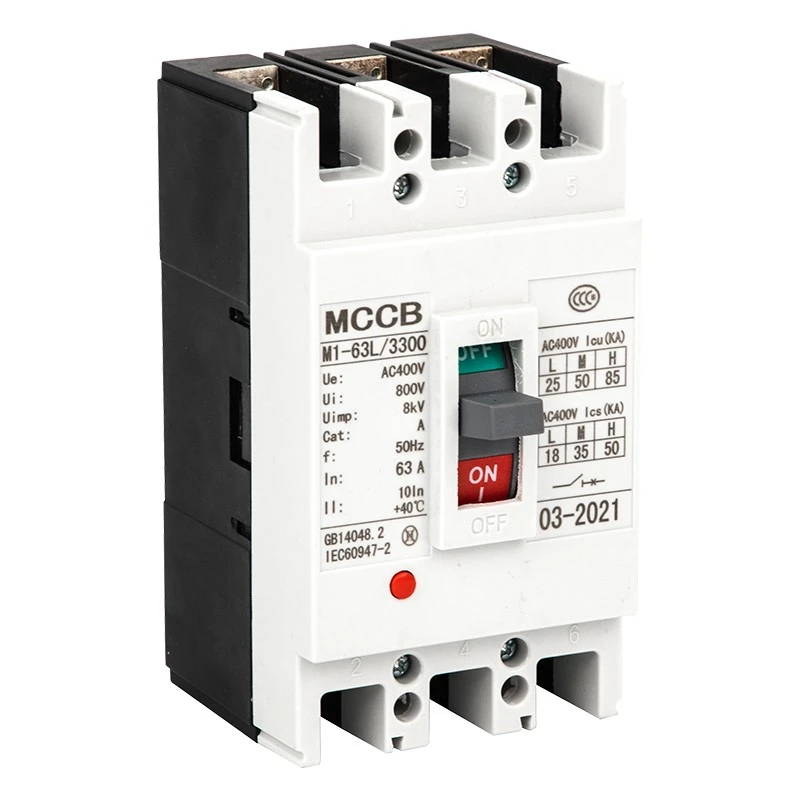
CM1 Moulded Case Circuit Breaker
This CDADA CM1 Moulded Case Circuit Breaker (MCCB) is built for bulk procurement, with IEC60947-2 certification and stable performance for industrial power systems. The CM1 MCCB uses high-strength structure and reliable tripping mechanism, easy to install and maintain. It combines intelligent protection with durable design, ensuring long service life in power distribution and heavy industrial applications.
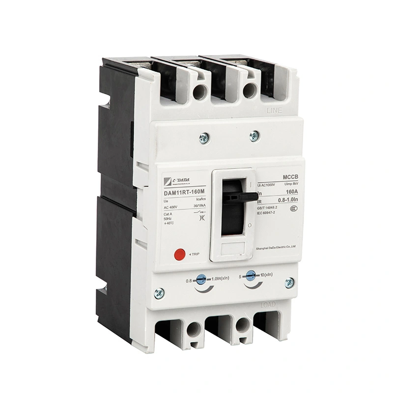
160A Thermal Magnetic Adjustable MCCB
CDADA is the manufacturer of 160A Thermal magnetic adjustable MCCB, our product is ideal for bulk procurement, a high-performance moulded case circuit breaker certified with IEC60947-2 for industrial power distribution. This MCCB uses current-limiting structure and modular accessories, easy to install and maintain. It combines adjustable tripping with patented contact design, achieving long life and stable circuit protection.
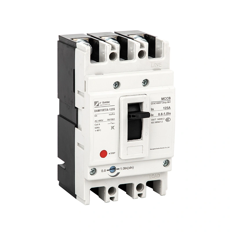
125A Adjustable Moulded Case Circuit Breaker
125A Adjustable Moulded Case Circuit Breaker is one of CDADA's products, as a professional factory, our product is high-performance with IEC60947-2 certification for reliable power distribution. It features current-limiting design and modular accessories, easy to install and maintain. It combines adjustable tripping with patented contact structure, achieving long life and stable protection for industrial circuits.
Thermal Magnetic Adjustable MCCB
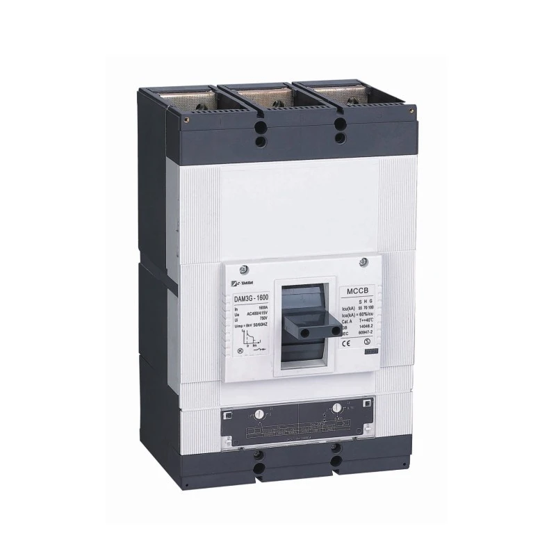
Source high quality Thermal Magnetic Adjustable MCCB from Shanghai DADA Electric, a professional manufacturer with 40+ years of experience. Our product is certified (CE, CB, ASTA), with adjustable thermal (70–100% In) & magnetic (5–10×In) settings. Ideal for precise protection in industrial panels. 250A to 1600A, 3P/4P, compact & globally compliant.

Thermal Adjustable Moulded Case Circuit Breaker
Discover the CDADA DAM1 Series Thermal Adjustable Moulded Case Circuit Breaker from 贴the reliable factory, Shanghai DADA Electric—certified (ASTA, KEMA, CE) and adjustable thermal settings (70-100% In). Ideal for precise overload protection in industrial applications. Available in 3P/4P configurations up to 1600A at 400V/415V. Perfect for OEMs and bulk buyers.
CDADA is a Moulded Case Circuit Breaker manufacturer and supplier in China. Our factory serves diverse industries such as power systems, building automation, and industrial manufacturing, offering flexible OEM/ODM solutions.