DAB6-63 Miniature Circuit Breaker: One Frame, 6 A to 63 A, One to Four Poles
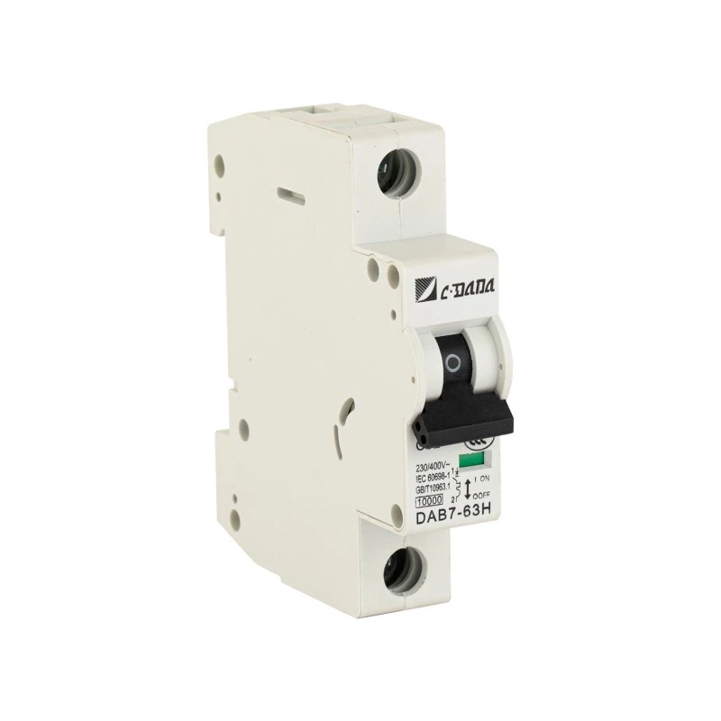
A distribution board commonly carries three or four different breaker types, because the loads it serves are different: lighting on one range, socket circuits on another, a pump or a hoist on a third. The DAB6-63 series is designed to simplify that arrangement. A single 63 A frame, a single accessory family and a single rail footprint cover 6 A to 63 A, one pole to four, three tripping curves and two breaking capacities, all mounted on \(35~\mathrm{mm}\) DIN rail.
The result is a panel that is quicker to build, simpler to stock and easier to present at inspection. Every device in the row shares the same \(80.2~\mathrm{mm}\) height and \(76.5~\mathrm{mm}\) depth, so comb busbars fit without adapters, covers close cleanly, and a replacement is one part number rather than four.
|
|
|
|
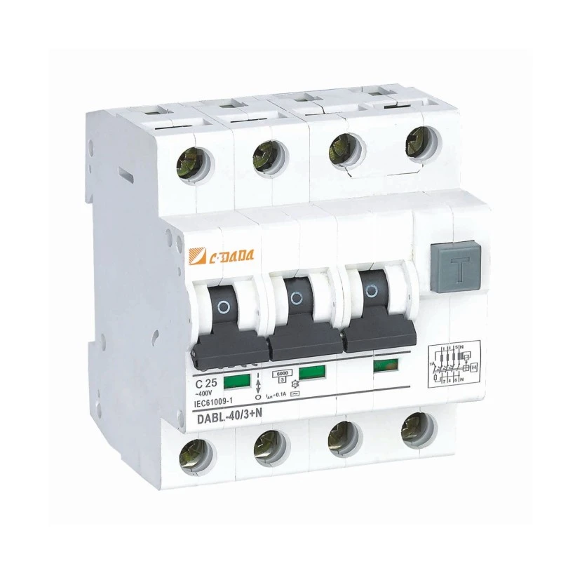
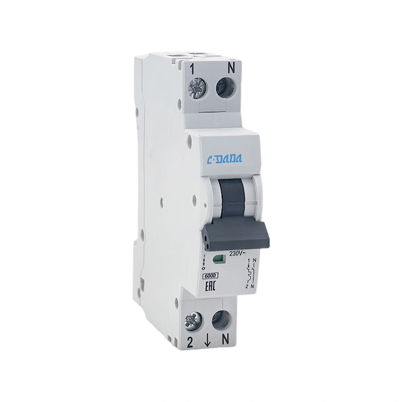
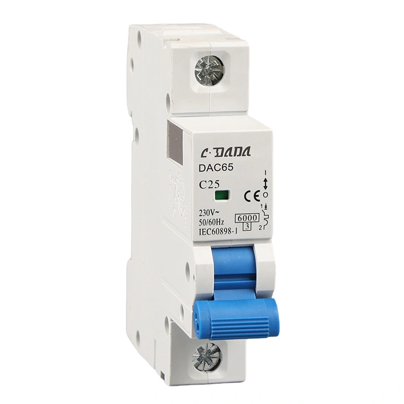
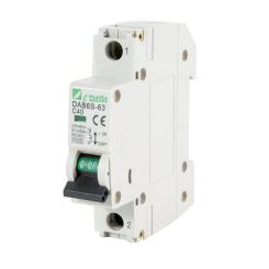
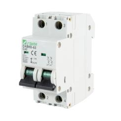
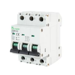
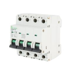
| 1P · 17.5 mm | 2P · 35 mm | 3P · 52.5 mm | 4P · 70 mm |
1. Four load types, three curves
The DAB6-63 is a thermal-magnetic device: a bimetal element provides overload protection and a solenoid provides short-circuit protection. What differs between the B, C and D versions is the instantaneous threshold, and that is what allows one frame to serve an entire building.
- B curve - lighting and appliance circuits with negligible inrush, the established choice for socket outlets and luminaires.
- C curve - drives with moderate starting currents such as compressors, fan groups and small pumps, and the most frequently specified version on mixed commercial boards.
- D curve - drives with high starting currents such as hoisting mechanisms and larger pumps, where the motor draws several times rated current for a fraction of a second.
Matching the curve to the load is what keeps a board quiet in service. Where a motor develops a high inrush, the D curve accommodates it from the first start while preserving the overload protection the cable requires.
2. Technical specification
| Parameter | DAB6-63 |
|---|---|
| Standard | IEC/EN 60898-1, GB 10963.1 |
| Poles | 1P, 2P, 3P, 4P |
| Rated current In | 6, 10, 16, 20, 25, 32, 40, 50, 63 A |
| Tripping curve | B/C/D |
| Rated voltage Ue | 230/400 V AC (1P, 2P) · 400 V AC (3P, 4P) |
| Rated insulation voltage Ui | 500 V |
| Impulse withstand Uimp | 4 kV |
| Rated short-circuit capacity Icn | 4.5 kA (DAB6-63N) · 6 kA (DAB6-63H) |
| Release type | Thermal-magnetic |
| Frequency | 50/60 Hz |
| Mechanical life | 20,000 operations (tested) |
| Electrical life | 8,000 operations (tested) |
| Terminal capacity | 1–35 mm² |
| Protection degree | IP20 |
| Mounting | 35 mm DIN rail |
| Dimensions W × H × D | 17.5/35/52.5/70×80.2×76.5 mm |
3. Construction details that matter on site
Four design decisions in this range are directed at the work an electrician performs at the board rather than at the appearance of the device.
- Notched terminal clamps. The notches engage the conductor directly rather than relying on flat-plate friction, which lowers thermal loss at the joint and improves mechanical stability. In service this is a terminal that remains cool under routine thermographic inspection.
- A wider engagement lever with a larger contact area. The increased contact area reduces resistance and heating at the current path, and the lever remains easy to operate with a gloved hand.
- Two forms of short-circuit protection within one device: thermal for sustained overload and magnetic for fault current, with no external coordination or setting required.
A common \(80.2\times 76.5\) mm profile across all four pole versions. Rows align, comb busbars fit without adapters, and spare-parts inventory is one item rather than four.
4. The range at a glance
| Poles | Width | Rated voltage | Typical application |
|---|---|---|---|
| 1P | 17.5 mm | 230/400 V AC | Lighting and socket circuits, single-phase final circuits |
| 2P | 35 mm | 230/400 V AC | Single-phase circuits requiring both poles switched |
| 3P | 52.5 mm | 400 V AC | Three-phase motors, pumps and small distribution feeders |
| 4P | 70 mm | 400 V AC | Three-phase plus neutral: mixed boards and sub-mains with neutral |
5. Two breaking capacities, one selection principle
The series is offered at \(4.5\mathrm{kA}\) (DAB6-63N) and \(6\mathrm{kA}\) (DAB6-63H). The difference is not one of grade but of suitability for the board in which the device is installed. The governing figure is the prospective short-circuit current at the point of installation, which is a property of the supply and the cable run rather than of the breaker.
In practice, the \(4.5\mathrm{kA}\) variant serves most final distribution boards fed from a moderate transformer over a reasonable cable length. The \(6\mathrm{kA}\) variant is the appropriate specification where the board sits close to the supply transformer, where the utility fault level is high, or where design margin is limited. Selecting from the calculated fault level and adding the margin required by the project keeps both cost and compliance in balance.
6. Accessories that complete the board
All four pole versions accept the same clip-on accessory family, so a board can be specified complete at the outset:
- Auxiliary contact — reports breaker position to a control system or indicator
- Alarm contact — signals that the device has tripped
- Shunt release — remote tripping from a fire panel or emergency stop circuit
- Undervoltage release — opens the circuit when supply voltage falls away
- Combined auxiliary and alarm contact, where panel space is limited
7. Frequently asked questions
What distinguishes DAB6-63N from DAB6-63H?
The distinction lies in breaking capacity. DAB6-63N is rated 4.5 kA and DAB6-63H is rated 6 kA. Both are thermal-magnetic, both are available in B, C and D curves across 6 A to 63 A, and both share identical dimensions and accessories, so the choice is made on the prospective short-circuit current at the installation point.
Can 1P and 4P devices be installed in the same row?
Yes. All four versions are \(80.2 \mathrm{mm}\) high and \(76.5 \mathrm{mm}\) deep, with widths increasing in \(17.5 \mathrm{mm}\) modules per pole. 1P, 2P, 3P and 4P devices therefore align on a \(35 \mathrm{mm}\) DIN rail, and a comb busbar can be cut to the row without adapters.
Which curve is recommended for a pump?
For a pump with a high starting current, the D curve is the appropriate selection; for a pump or fan with a moderate starting current, the C curve is normally sufficient. Where nuisance tripping occurs at start-up, adjusting the curve preserves the overload protection the cable requires, while increasing the rating does not.
Related News
- How Does a 2P 4P Electronic Type RCBO Improve Electrical Circuit Protection?
- How Does a 2P 4P Electromagnetic RCBO Improve Electrical Safety and Circuit Protection?
- How Does an NSX Moulded Case Circuit Breaker Protect Electrical Distribution Systems?
- What Is a Type A Residual Current Circuit Breaker and How Does It Protect Electrical Systems?
- What Makes an MCCB with Leakage Protection Important for Safer Power Distribution?
- What Makes a 125A 15kA Miniature Circuit Breaker Suitable for High-Current Protection?
Leave me a message
New Products
News Recommendations